CREEPMETERS
A creepmeter is an instrument that monitors the slow surface displacement of an active fault. Its function is not to measure fault slip during earthquakes, but to record the slow aseismic slip between earthquakes. The measurement range of a creepmeter is usually limited to 10-30 mm. Data are typically recorded once every 1 to 10 minutes.
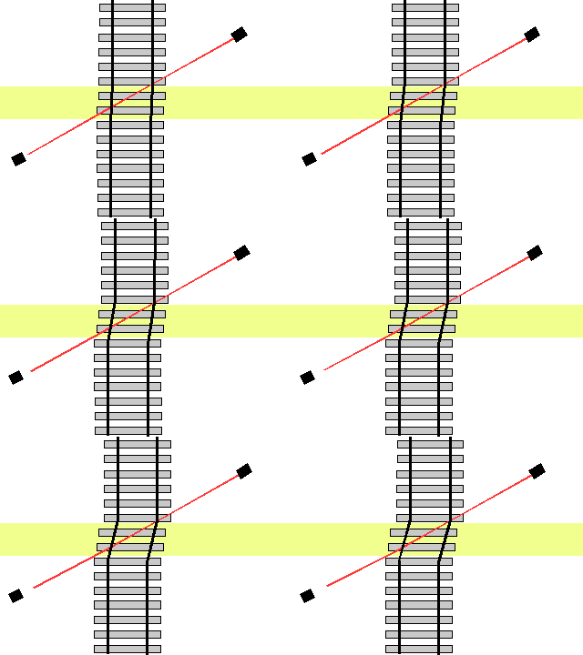
Creep may be continuous or episodic, occurring as creep "events" with amplitudes of 1-10 mm and with duration of 1 hour to several days. The offset of the rail-line below occurs in two creep events.
Most creepmeters operate by monitoring the free end of a length standard (a rod whose length does not change) installed 30 cm-1 m underground and obliquely across a fault. In the map view of the fault zone (green-yellow) below, a creepmeter rod (red) is installed at 30 degrees to the fault. Note how the gap between the lower left end mount increases as dextral slip increases on the fault.
The measured displacement is reduced by the obliquity of the creepmeter. e.g. if the rod were normal to the fault it would sense no creep. The measured LVDT displacement must be increased by 1/cos(Ω), where Ω degrees is the angle of the rod where it crosses the fault. Since this changes slightly during each creep event, the starting obliquity must be less than 30 degrees to preserve 1% accuracy for creep of tens of cm. If the fault is narrow it is sometimes necessary to reinstall the rod after a decade of creep to ensure linear behavior.

The length standard is made from invar (a 36% Ni Iron alloy), carbon fiber, or quartz fiber, all with thermal coefficients close to 1 ppm per degree Celsius. The rod is typically 6 mm-12 mm in diameter and is placed within a low-friction telescopic plastic jacket.
If the fault is narrow, a suspended catenary of invar wire held in tension by a beam balance can be used, but in many cases the fault is several meters wide requiring a creepmeter rod length of 30 m or more.
The changing gap width is typically measured with a Linear Variable Differential Transformer (LVDT). This device consists of three coils, the central coil energized with a 5 kHz signal, the magnetic flux from which is linked to the outer two by a ferrite rod. Coaxial motion of the ferrite core changes the voltage and polarity derived from the AC voltage sum of the two outer coils. Displacements of 1 µm are relatively easily detected.
The black squares represent end-mounts that must faithfully record the position of each side of the fault. Engineered mounts consist of helical piles driven in the form of a buried tripod, or drilled columns that include a tiltmeter. These mounts are anchored at depths of 10-30 m and typically provide 1 mm annual stability even in expansive clay environments. In many installations engineered end mounts are too costly to install, and concrete and reinforcing bar are used to form a monolithic block that samples the average position of near surface soils or gravels. Since the depths of these handmade mounts is less than 2 m, they tend to be sensitive to the effects of soil moisture and temperature, resulting in noisy seasonal records. Notwithstanding the long period noise, creep events tend to be recorded clearly becuase they are of shorter duration than most climatic changes.
The creepmeter below passes beneath a railway line that has been offset by the San Andreas fault (white dashed line) in the Coachella Valley. The rocks on either side of the fault have different colors and the creepmeter is installed at 30° obliquely beneath the rail line.

Creep on the San Andreas fault has offset the two rails of the Southern Pacific railway line by approximately 8 cm since it was installed in the early 20th century. This creep has been observed to be triggered by eartqhaukes on nearby faults. The line is disused and is slowly being buried by alluvium. The white and rusty area of the distant rail above was exhumed for the photo below.
