FAQ AMS Hardware
This is a list of Frequently Asked Questions (FAQs) about Aerodyne Aerosol Mass Spectrometer (AMS) hardware. The initial list is based on the presentation by Ed Fortner and Bill Brooks of Aerodyne (with input from Wade Robinson and John Jayne) at the 10th AMS Users Meeting in Toronto, Canada. Anyone from the AMS Community is welcome to add to the questions and answers. If you don't have a Wiki account yet, you can request one by clicking here.
Recommended AMS Maintenance
- Clean fan filters on all electronic components and Turbo Pump fans
- Check and tighten 80/20 (frame) fasteners after shipping
- Clean the instrument, particularly the raw aluminum chamber surface. Avoid exposure to elements, especially sea salt.
- Computer Hard Drive maintenance
- Always keep the vacuum system operational, Don’t leave instrument in the powered down state for extended periods (> 1-2 weeks).
- Check the health of the chopper servo by running the "Top Hat" software check
Frequently Asked Questions
General FAQs
How much information does Aerodyne need to help me diagnose my problem?
A: as much as possible. E.g. we often get questions such as "The AB is low, what should I do?". It is impossible to know what the cause his without knowing many additional pieces of information, such as your flow rate, state of pumping system, MCP voltage, single ion measurement, etc.
I have questions about AMS Software
The FAQs and information about AMS software are kept in separate Wiki pages:
- FAQs for ToF-AMS Data Acquisition software (DAQ)
- FAQs for ToF-AMS Data Analysis software (Squirrel, PIKA, APES, etc.)
- Guide for PMF analysis of AMS data (PET)
I have questions about what the AMS data mean
We also keep a separate Wiki page with FAQs for AMS data users
Is there a general diagram of the signals and connections in the ToF-AMS?
Yes! and it is posted below. This diagram was developed by Weiwei Hu (Peking Univ.) during her stay with the Jimenez group.

Vacuum System FAQs
What are the operating currents for all pumps?
(Generic values for currents measured using the new pump box (silver, with digital display)
| Pump Number | Gas Load Off (mA) | Gas Load On (mA) | Delta T(C) (Closed) (&) | Delta T(C) (Open) (&) |
|---|---|---|---|---|
| P2 | 450 | 850 | 9 | 13.3 |
| P3 | 250 | 300 | 9 | 9.3 |
| P4 | 200 | 250 | 6 | 6 |
| P5 | < 200 | < 200 | 6.2 | 6.5 |
| P5 | ~200 | ~200 | 9.6 | 9.6 |
(&) Delta T = Pump Temp – Ambient Temp
What are your backing pump pressure and lens pressure?
Answer: you can read both of them with the same 10 Torr Baratron pressure gage (displayed in the electronics box). There is a 3-way valve, when pointing up if reads the lens P, when pointing down in reads the backing pump P.
Why is my flow rate so high?
A: The key here is that the AMS does not measure a flow. It is measuring the pressure in the lens using a 10 Torr Baratron gage, and a calculation is done in the DAQ software to give the flow rate. So if you are measuring the backing pump pressure then you will have a flow rate value (as displayed by the DAQ software) which will be much higher than expected. Simply turn the valve on the front of the AMS to measure the lens pressure and your flow rate will be correct.
If one turbo pump fails can I keep running the system?
Answer: NO !!! This may kill several other pumps (and that has actually happened to at least one group).
Can I keep a spare turbo pump in its box for a year?
A: No!!! If you do that, the lubricant in the pump bearings will phase-separate, and the pump will likely fail shortly after being installed. Every pump should be spun at least every 9 months for a minimum of 30 minutes. If possible the 'soft startup' mode that is designed into the varian controller/t+ software is preferable. If a pump sits for longer than 10 months it is recommended that the pump be sent back to varian for re-channeling (~$450.00)
How can I check whether my instrument is leak-tight?
A: turn the pumps off and close the valve between the turbo pumps and the diaphragm (backing) pump. Tend record the increase on the pressure of teh vacuum chamber (with the lens P meter) vs. time. The leak rate should be a fraction of 1 Torr per day, and in a really good instrument (such as the CU AMS during ARCTAS it was less than 0.1 Torr/day).
What is the fitting on the MD1?
This is a BSP/ISO parallel thread that replaces the standard hose barb fitting that is delivered with the MD1.
Swagelok part
SS-2-A-2RS adapter, female NPT to BSP/ISO parallel
S-2-RS-2V gasket for RS fitting
which has a 1/8" FNPT on the other end.
Proper Turbo Venting according to Varian
- Varian bearing purge and turbo pump shutdown here
- Do not let the turbo pumps spin to zero in vacuum without venting.
- Instead leave the diaphragm pump on and crack vent ports slowly on pump 5 (v301) and pump 6 (v81) until you hear a slight hiss. Keep those vent ports at that setting for ~3 minutes.
- Once turbos have reached about 6000 rpm then it is safe for the user to break vacuum in the system as well as turn off the diaphragm pump.
Inlet FAQs
When should I align the lens?
Answer: After shipping or if there is reason to believe that the instrument has been bumped. In most instances the alignment won't change, but if it happens to change it can have catastrophic consequences for your data, if you don't check before the measurements. We know that this problem has degraded data for several campaigns of several prominent groups in the AMS community.
Component FAQs
How do I change my MCPs?
A: See: Directions for changing MCP (movie) (password protected)
When can I turn on the MCP after venting?
A: It depends. It is always best to pump overnight, but if the system has only been vented an hour or two, and there is a need to collect data right away then after about 1/1.5 hours.
When can I turn on the filaments after venting?
A: About 45 minutes.
At which point were different updates to the AMS electronics introduced?
- Chopper circuit upgrade: New 14 pin connector, not back compatible (starting with instrument 215-073)
- HB display is now real (Rev L 215-077)
- Improved 24V amperage reading on Pump Box (215-085)
- New pump controller firmware features:
- Master Interlock > V4.1 (215-070)
- Selective pump on/off control
What is the replacement for the dust filter in front of the fans on the electronics box
- Replacement comes as full plastic and filter assembly from SPC technology
- Part number is 2482 and is approximately two dollars.
What are the pin-outs for the blue-connector cable leading from the 6024E card to the BNC terminal block?
- The fat cable with blue connectors is NI model SH-68, see details here.
HEATER details
- The heater voltages are provided by a circuit board in the electronics box, and are routed into the TOF via the TPS and the "filament" feed-through plug. The TPS does NOT DO ANYTHING other than loop the incoming heater voltages from the e-box directly to the TOF.
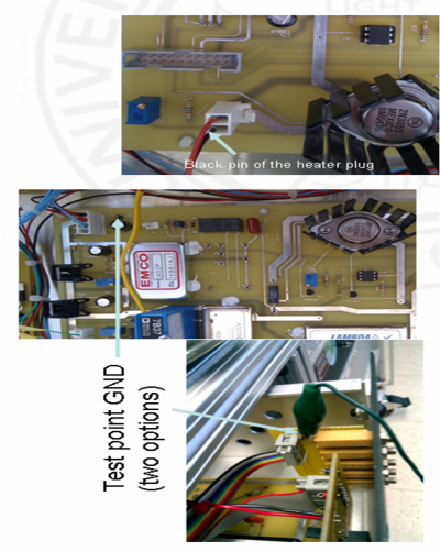
- The +ve and -ve voltages have multiple places in which they could get switched: the cable, the feed-through and at the point of attachment on the ion-optic stack. Thus we have "positive" and "negative" polarity instrumental setups. If the heater fails to warm-up under load, it is likely wired backwards; to change the polarity one simply reverses the orientation of the heater plug (the small white one in the top right hand pic on pg1 of the ppt).
- Procedures to measure, calibrate and troubleshoot heater board voltages (ppt)
CHOPPER details
- The chopper assembly contains three principal electronic parts:
- Motor to spin chopper wheel. For old electronics boxes this is part 1525-UO12-BRE from MicroMo, and is a discontinued part. For new e-boxes, this has been superseded by part 1525-BRC, see spec sheet. You cannot update your chopper motor without also changing the chopper circuit board in the electronics box... the new and old version are NOT compatible.
- Servo motor to move chopper in and out of particle beam. Part HS-81 from hitecrcd.com Also Hitec HS-85MG+ is the same servo motor with a metal gear as opposed to nylon which may increase the longevity of the motor (same shape and power requirement as the HS-81).
- Honeywell optosensor to return chopper wheel position signal to electronics.
- Screws to attached chopper wheel to chopper motor adapter are 2-56 thread (~1/4 inch).
- SERVO OPERATION & TROUBLESHOOTING
- In replacing the servo, it is essential to re-calibrate the servo open/chopped/blocked positions in the DAQ. A warning is also given to take care that the chopper wheel does not end up impacting on any surrounding surfaces at the limits of the servo movement.
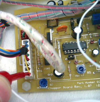
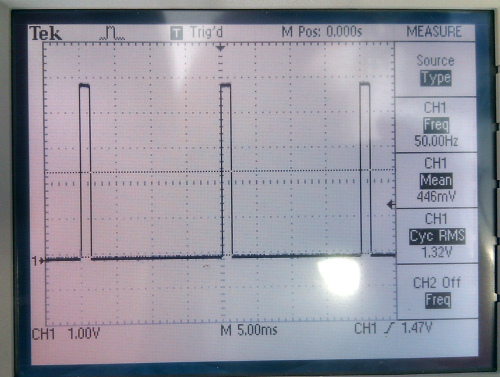
- The position of the servo is controlled by a square-waveform output, the duty-cyle of which determines the servo position. Before breaking vacuum to check the servo, it is recommended to verify this waveform is being passed correctly to the chopper assembly. The waveform is measured at pin 8 of the large white connector on the chopper board:
It should be a clean square wave; watch for it to change in width when toggling the servo movement using the DAQ/Critter.
- OPTOSENSOR OPERATION & TROUBLESHOOTING
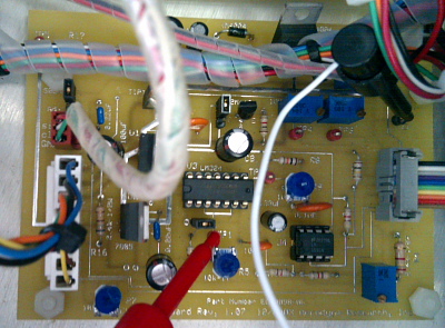
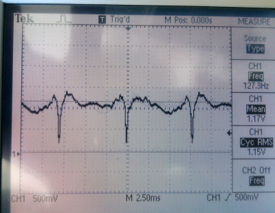
- The optosensor output signal is sent to the chopper comparator circuit to be transformed to a clean square-waveform for input to the NI6602 timer card. In revision 1.xx of the chopper board, this is performed by comparison to a manual threshold voltage; this process is described in this pdf. The new chopper board has an "automatic" comparator. In both, the signal from the optosensor can be measured at TP1:
Variations in the reflectivity of the chopper wheel will propagate into the optosensor signal, but the positions of the slits should be very obvious:
- Links to spec sheets and electronics layouts relevant to the CHOPPER
PUMP details
- The AMS vacuum system is backed by an MD1 diaphragm pump (24V version). The base pressure of this pump is a little under 2 mbar, and is required in the chamber to start the turbos.
- Spec sheet and safety details for the Varian V301 Navigator turbo pumps.
- Spec sheet and safety details for the Varian V81 (or 70 on older systems) turbo pumps.
Is there a diagram of all the voltages in the TOF ?
Yes, it is here with the usual username and password.
Troubleshooting FAQs
My Airbeam is low
- There are many possible causes of a low airbeam, but you should check:
- Is your valve open? Is your lens pressure normal (~1.5 Torr)? Is your flowrate normal?
- Is your heater bias on and at the correct value?
- Is your m/z calibration correct?
- Is your mass spectrometer poorly tuned?
- Are the electronic baseline and, more pertinently, the single-ion area, correctly defined in the Bitwise panel?
- Is your detector (MCP or multipler) spent? Or does its voltage need to be increased?
- Is the chopper servo not moving, or moving erratically?
- Are the chopper positions correct (see Servo panel)?
I see small reflection peaks following all peaks in my mass spectra and in the Bitwise SI trace
This problem is generally due to loose or missing connections in the pre-amp assembly. See instructions for diagnosing.
I have MS, but not a PTOF airbeam
- Check the MS AB is representative, for example with the procedures outlined in the list above, particularly the servo positions. Then consider the following:
- Is the toggle set appropriately in the DAQ timing panel (50 or 100ms)? This can be checked by looking at the m/z 28 peak in Bitwise; if the %age probability of returning a peak per extraction is not significantly higher than for the single ions, the toggle is probably on the wrong setting.
- Is the timing correct? If the default values entered for m/z cal are not accurate, you may have been mislead about the PTOF timing settings. Leaving an insufficient time after the end of each extraction has been known to return null PTOF mass spectra.
I don't have a PToF Airbeam after I shipped the instrument
- This problem is often caused by the timer card being unseated during transport. The fix to try is to shut down the computer, open it, take the timer card out and put it back in (making sure it is well-seated in the PCI slot) and trying again.
My chopper servo is not moving
- Question: we're having a problem with the chopper servo (it doesn't move). We tried swapping in a new servo motor with no effect, making me think that the problem is with the chopper board itself. The chopper still spins, and we found pins in the chopper cable carrying 12V and ~3.7V, which I think are the chopper and servo power, respectively. None of the cable pins showed a voltmeter response to changing the servo position through the software (DAQ or CRITR), though I'm not sure how/where to measure this.
- Reply: it sounds like you are missing the PWM signal that positions the servo. This is the yellow wire on the servo. The red wire is the 3.7V that you measured and black is ground. The PWM signal originates from the 6024 NI card, usually CTR0 routed to USER1 or USER2 BNC, the small jumper wire on the BNC2090 i/o panel. I would try connecting the appropriate USER BNC to a scope and use CRITR to vary the signal. You should see a variable width (1-2 ms) repeating at 50 Hz. If you don't see this there is something wrong with the NI card.
My PToF AB appears as two peaks
(Documented by Roya Bahreini)
After a few hours of data acquisition, the double-peak would come back repeatedly. It improved temporarily with changes in the chopper frequency while changes in the timing parameters did not make a difference.
Note that the ‘double peak’ can also be present for particles pToF signal, but that’s trickier to catch unless one is sampling mono-dispersed particles.
I looked at the chopper signal (Tee’d into the line that goes to the timing card) on the scope (It’s better to zoom in to see 2 cycles). In one of the cycles, there was a ‘blip’ before the opening signal of the chopper, peaking ~ 2-3 V. The 2nd cycle had no ‘blip’.
It’s possible then that the timer card was being triggered with the ‘blip’ on half of the cycles and therefore Time Zero of the pToF two chopper cycles was not the same, leading to a double peak.
To fix the problem, first, check the comparator signal of the chopper circuit and set it to ½ photodiode signal as explained in the link below if it’s not set properly http://cires.colorado.edu/jimenez-group/QAMSResources/Docs/Chopper_VrefSetpoint.pdf
If this doesn’t take care of the double peak, remove the chopper flange to make sure chopper assembly is well fixed and not wiggly. Now that the system is open you might as well clean the surface of the chopper and the photodiode as well!
If the problem is still there, maybe the timing card or timing card cable need to be replaced.
My heater current looks correct (1-1.1 A), but I don't think it is 600C
- As per Leah Williams' presentation at the 2010 AMS users clinic, the AMS heater current should be in the region 1 to 1.1 Amps for a temperature of 600C. However, if you have this current dialed in, but have reason to believe the heater /= 600C (ie it is glowing red hot or you are not vapourising species), the potentiometers which calibrate the LCD readout may need adjusting. Follow the instructions on this ppt file.
I have problems with my heater voltages
Heater voltages
- The reference voltage applied at the heater is not at ground, but rather at a positive value known as the “Heater Bias”
- The true bias voltage can be measured from test-point-GND to the black pin of the heater plug
- The value on the LCD screen can be calibrated to the measured value using potentiometer R10
- The “heater power” voltage is that across the black and red pins on the plug
- The LCD readout can be calibrated using the process described on the following slide
The “heater power” voltage should be ~10V with the plug disconnected. If this is not the case, the board needs troubleshooting
Calibrating heater power voltage
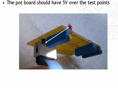
- Turn pot 1 until voltage measured across white pins matches front screen
- Turn “Heater Power” pot on front to max (fully CW)
- Turn pot 2 until reach 2A on front screen
- Repeat step 1.Turn “Heater Power” down as appropriate
Heater bias is tied to ground
- This indicates a short somewhere in (probably) the TOF
- Thermocouple wire touching anywhere on the assembly would induce this problem
- Note that the HB voltage is also applied to the thermocouple, owing to its placement at the heater tip
Troubleshooting heater power failure
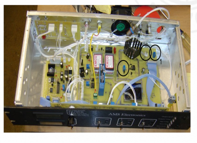
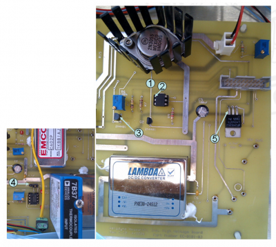
- Base of the large transistor 2N3055 (point 1) should be at 12V referenced to the black pin of the heater plug
- Pin 1 of the optical isolator (6-pin chip) (point 2 on photo) should be at 5V referenced to TP-GND… when the heater power switch in on
- The base of transistor Q1 (central pin, point 3 on photo) should be at 5V referenced to TP-GND
- 5V regulator at point 4 should be at 5V ref. to TP-GND
- Circuit 5V at point 5 should be at 5V ref. to the black pin of the heater plug
