Updated 02-June-2006, JRK
The ToF-AMS Instrument Control and Data Acquisition Software is a custom application for operating an Aerodyne Time-of-Flight Mass Spectrometer. It includes features for:
Installation on a New Instrument
Multiple Menu Files
In many applications it is desirable to switch quickly between modes of operation of the ToF-AMS. Examples
include different modes for vertical profiling vs. horizontal sampling in aircraft, or switching between the
V and W modes of the high resolution ToF-AMS. Most of this can be done by switching between different menu
files.
At load, the software defaults to ToFAMSMenu.prm, which is the only required parameter file. Up to 3 additional menus may be read by the software. These should be added to the C:\ToFAMS\ToFAMSCode directory with the filenames: ToFAMSMenu_A2.prm, ToFAMSMenu_A3.prm, or ToFAMSMenu_A4.prm. These files are most easily created by renaming a copy of ToFAMSMenu.prm.
Buttons for each menu appear to the right of the parameter menu form. The active menu is highlighted in green. The active menu is changed by pressing one of the other buttons.
Automatic Menu File Back-Up
At the start of the software, back-up copies of all menus are written to the directory C:\ToFAMS\ToFAMSData\LogFiles\MenuCopies
Copies of the default start menu (#1) have names of the form: YYMMDD_StartMenu.prm
Copies of the additional menus (#2-4) have names of the form: YYMMDD_ToFAMSMenu_A#.prm (where # = 2,3, or 4)
A given menu file is backed-up only one time per day. If, at the start-up of the software, a copy already exists with the current date the menu is not backed-up. Note that in earlier versions, menu #1 was backed-up daily to the directory C:\ToFAMS\ToFAMSData\LogFiles
Other Menu "Safety" Features:
Timed, Automatic Menu Switching
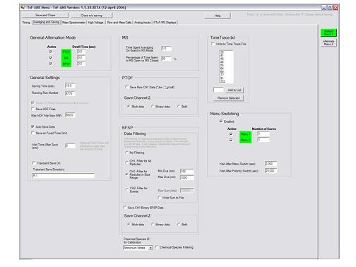
For any acquisition mode (PToF, MS, or GenAlt) the user may choose to automatically alternate between menu files (*.prm). This feature is enabled from the Menu Parameter Window, where the user also selects those menu files that will be switched between and the number of runs to spend at each menu.
( Timing )
( Averaging and Saving )
( High Voltage )
( Flow and Mass Calibration )
( Mass Spectrometer )
( PToF / MS Displays )
( Analog Inputs )

General Alternation Mode
In General Alternation mode (toggle mode), data may be acquired by stepping through PToF, MS, and/or
BFSP modes (see below). The user chooses which modes should be active and sets a dwell times for each.
Modes are actived by checking the corresponding boxes in the General Alternation Mode Box. The active modes are highlighted in Green, and inactive are gray. The sum of the dwell times approximately defines the time precision with which you can save files.
Fixed Time Grid Saving
Fixed Time Grid Saving forces saves to occur at clock times that are integer multiples of the defined save time. For instance, with a save time of 5 minute the software will save at :00, :05, :10 … etc.
Optional Wait Time After Save
This feature forces a fixed delay in acquisition after each save. It can be used if you have a switching setup that you want to sample and bypass at regular intervals (such as a thermal denuder, a CVI, etc.) on the front end of the AMS, and there is some time involved with switching between modes (due to dead time in the plumbing, etc.). When this value is > 0, the data acquisition does not begin until the specified time has elapsed. The default value 0 does not discard any data.
Transient Saving
Transient File Saving creates a second copy of the *.itx data in a directory specified by the user. *.bin files are not copied. This may be useful as a way to transfer data to another system, or to save a backup copy of the data on a second hard drive.
If the “transient folder” path does not exist then files are only saved in the Autosave folder.
Warning: if the specified “transient directory” has fewer than 2MB of free space remaining, all .itx files in that directory will be erased. This does not affect the principal Autosavedata folder.
User-selected data file types (itx and/or .hdf)
Checkboxes allow the user to determine whether data will be saved in IGOR text and/or HDF5 formats. At present, the "Save ITX Files" checkboxs Defaults to Yes, and *.itx data are always written. The "Save HDF Files checkbox" determines whether data is saved in HDF5 format. (Note that this is different than the HDF4 format that is available on the Q-AMS acquisition software.) At present, HDF5 format is possible for MS and PToF data, but not BFSP. If HDF5 data is saved, directories will be created for for AutoSave and NonAutoSave HDF data.
C:\ToFAMS\ToFAMSData\AutoSaveDataHDF
C:\ToFAMS\ToFAMSData\NonAutoSaveDataHDF
Saved HDF files can be viewed in IGOR (version 5.04, using HDF5XOP) and processed with SQUIRREL.
Multiple acquisition runs are written to a single HDF5 file.The "Max HDF File Size" text boxes sets the upper limit for the size of generated HDF5 files. A typical value is 600 MB.
TimeTrace.txt
TimeTrace.txt is a tab-delimited text file saved in the directory C:\ToFAMS\ToFAMSData\LogFiles\TimeTrace
If the "Write To Time Trace File" checkbox is selected, a unique line is written to the file TimeTrace.txt at each run save. This file is meant to be used for gaining a quick look at trends in the data. Each run line includes time of save, air beam values, loadings, and MS intensities for m/z 43, 44, 57, and 10 user-selected values. For more details see the Saving section later in the manual.
The user-selected m/z values default to: m/z = 30, 41, 46, 48, 55, 64, 69, 77, 91, and 202. These 10 values can be changed in the list box below the Write to Time Trace File checkbox. Only 10 values are allowed, and if fewer than 10 values are selected, unused default values will be included in the file, starting with lowest unused m/z.
MS On Board Averaging Time
This value determines how long the acquisition board averages in each phase of MS mode (open and closed). The default value is 3 seconds. Each transfer of data from the acquisition board requires a certain dead time, and there is a dead time after each movement of the chopper. So, unless conducting experiments with very high time resolution, this value should not be set lower than the default. For fast experiments, users should also adjust the MS Open/ MS Closed ratio.
Variable MS Open / MS Closed Ratio
This ratio is meant to be adjusted only when data is being saved rapidly, and the user does not want to commit too much time to measuring the background signal (MS Closed).
The Percent MSOpen parameter takes a value between 0 and 100 percent. 0 being never open and 100% being always open.
A closed spectrum will be collected at the start of MS acquisition, even if this value is 100%.
If saves times are short and only an open or a closed spectrum is collected during the duration of a run the data file will contain only the aquired waves.
Caltech has used this mode in the airplane (summer 2005) with an effective time resolution of ~1.4 seconds. Again the Time spent averaging on board in MS mode will limit the speed at which you can save. If you want true 1 Hz data, you will need to set that time to less than 1 second (at present you’ll need to experiment with it until you get the approximate data rate you want).
The number of times through MS Open and MS Closed are saved in the info file as indexes 11 and 22 of the info wave, respectively.
PToF Data Saves
Brute Force Single Particle (BFSP) Data Filtering
BFSP filtering accepts or rejects data based on signal levels at m/z values corresponding to sulfate, nitrate, and organic species. If signals for any of these species are above a software defined threshold, the single particle file is saved. If not, the BFSP data is rejected and no file is saved. This drastically reduces the number of files saved to disk, but it could bias your data slightly based on the criteria used to identify single particles. A good way to make yourself familiar with
this mode is to sample monodisperse pure and mixed particles in the lab, and look at the detection rates as
a function of mobility diameter.
Filter for All Particles.
Data are saved for any chopper cycle containing a ToF extraction where one of the m/z sets 30/46,
48/64, or 43/57 cross a software-defined threshold together.
Filter for Particles in Size Range.
Like "Filter for All Particles" with the added stipulation that the TOF extraction where the m/z values
cross threshold must correspond to a particle size within the user defined range (Min Dva - Max Dva).
CH2: Filter for Events
Note: This feature was added specifically for ARI light scattering experiments.
Instead of filtering based on sulfate, nitrate, and organic signal levels, users may filter BFSP data based on the CH2 signal intensity. In this case, the BFSP data array is treated as the matrix with rows equal to the successive ToF-MS extractions. The elements of each row are summed, and the sums are compared to the user-defined Row Sum. If any row of the data set has a value greater than the Row Sum, data from both channels are saved. If not, data are rejected.
In order to determine appropriate thresholds, CH2 row sums may be saved during acquisition. With “Write Sums to File” checked (below filter choices), row sums will be written to the text file C:\ToFAMS\TestData\BFSPSegSums.txt (Only those values that are below threshold will be written.)
BFSP Data Saves
CH1 BFSP data are always saved as sticks. Raw BFSP data saves are optional. Data in these *.bin files are 8-bit unsigned integers. 8-bit values are created by converting the 32-bit values transferred from the board, in order to save hard disk space. If Co-Adds are used data values are divided by number of co-adds; this ensures data values < 256.
If CH2 acquisition is enabled, the user may choose to store CH2 sticks and/or CH2 raw data.
BFSP data is saved in the folder:
C:\ToFAMS\ToFAMSData\BFSPData
Files are named in with the format:
"DateString"_"RunNumber"_"choppernumber(per runNumber)"_BFSP
(eg, 050621_7243_16_BFSP.itx)
Warning: Raw BFSP files are large (~8MB) and could quickly fill up a hard drive (~8MB per file). If the spectrometer is well calibrated (for m/z), there is little additional information in the raw spectra. The expection would be the raw spectra from the vwToF that in may contain high resolution information for single particles, although with much reduced statistics due to the lower signal levels. To our knowledge this aspect has not been explored so far.
Menu Switching
With menu switching enabled, the software will alternate between menu files (*.prm) during acquisition. Checkboxes determine which menu files will be actively switched between. For each active menu, the Number of Saves Value
determines how many runs will be acquired before switching. As for ordinary operation, the duration of each run is the user-defined Save Time.
While acquiring in any mode (GenAlt, MS or PToF) the software will continuously loop through active menus, from lowest to highest menu number. The user-defined wait after menu switch allows TPS voltages to settle each time the menu is switched. This value defaults to 3 seconds, which is the recommended wait if TPS voltages are changing between menus - e.g, if switching between V- and W- modes. If all active menus have identical TPS settings, no wait is necessary. For the special case of switching between positive and negative ion acquisition (requires bipolar TPS), acquisition stalls for the user-defined wait after polarity switch, which defaults to 25 seconds.
The menu parameters AutoSaveOn, WriteHDF, MaxHDFFileSize, SaveFixedGrid, and noiseFilterThresh are set identical across all menus. All other parameter values may be uniquely controlled for each file.
If menu switching in General Aternation Mode, each menu may have different combinations of acquisition modes (i.e, MS, PToF, and BFSP) and different dwell times for each.
TPS Voltages
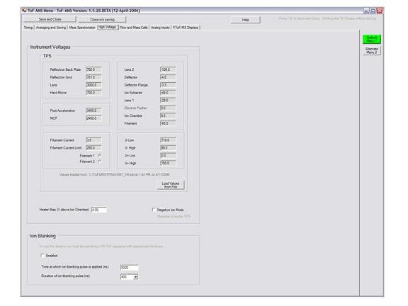
ToF Power Supply (TPS) voltages are stored as menu parameters #139-159 and displayed in the High Voltage Tab. These values are imported for each menu by loading the relevant TPS setting file (*.set). Only *.set file generated with TPS_Controller 2.05 or later may be loaded. Values for voltages cannot be entered manually. For each menu, the setting file path and time of load is displayed. Note that the setting file is loaded only once and is not monitored by the acquisition software. If changes are made to the setting file from the TPS software, the setting file must be re-loaded in order to make these changes in the menu file.
During acquisition, the ToF-AMS software will send control signals to the TPS Controller software. If remote control is enabled in TPS_Controller, these signals will cause the TPS voltages to update to the values displayed in the High Voltage Tab. Successful changes in TPS settings will be indicated by a label in the TPS Controller software. Use of this feature is required for automatic switching between menus that depend on different TPS voltage settings (e.g., V- and W modes). If TPS_Controller remote control is not enabled, the values displayed in the menu window will be saved to the ParVal waves, but they will have no effect on the actual TPS voltages..
Note: The TPS_controller software and related files should be saved to the directory C:\ToFAMS\TPS
Heater Bias Control
The acquisition software uses analog output channel 0 of the NI6024E to set the voltage of the heater bias power supply. For each menu, the user should input the heater bias voltage relative to the ion chamber voltage of the TPS. This user input is stored as the menu parameter heaterBiasV. At the load of each menu, the heater bias power supply will be set to a voltage equaling heaterBiasV plus the ion chamber voltage defined for the TPS. Without a value loaded from a *.set file, the ion chamber voltage is fixed at 0 V.
Use of this feature requires that a BNC cable be connected between analog output 0 of the NI6024E board, typically labeled as "DAC0" on a NI BNC-2090 connection accessory, and the proper connector on the back of the Aerodyne AMS Electronics box. Also the Heater control switch must be on "Computer" state.
Negative Ion Mode
Negative ion detection requires a bipolar TPS. The Negative Ion Mode checkbox should be set to indicate the mode of the
menu. This boolean value sets certain controls, including the necessary wait time after menu switching and the required polarity of the heater bias power supply.
Ion Blanking
Ion blanking requires a w-ToF equipped with ion blanking hardware. If enabled, ToF voltages are pulsed in order to eliminate certain m/z ions from the spectra. Ion blank time is the flight time at which the blanking event begins. As a first approximation, this should equal the flight time to the hard mirror for the m/z to be blanked. The blanking pulse will last for the user selected duration, between 100 nsec and 5 microsec.
Negative deviation from these values will cause the corresponding labels in the Mode Display Window to change color during acquisition. (For the case of Flow rate, positive deviation will also cause the label color change.) Orange indicates moderate deviation; Red indicates extreme deviation.
Standard Diagnostic values can be input in this window. Or, values can be captured during acquisition by pressing "Control-d".
Resolution Ratios compare the achieved m/z resolution to the resolution demonstrated for well-tuned ToF
instruments during tests by the Jimenez group in 2005.
Peak Monitoring in Mode Display
Users may closely monitor up to 3 different peaks in the mode display window (raw data display). The default
m/z values for display are set in this tab.
( AP240 ) ( Slow Board ) ( Instrument ) ( ID Values )
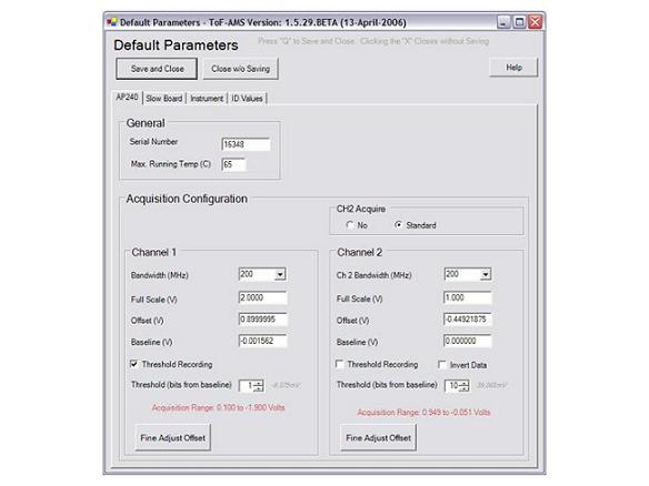
During acquisition, the measured card temperature is output as info value #45 and displayed on screen. A Warning will appear in the acquisition window when the card temperature reaches 60C. This alerts the user to the fact that the temperature is getting high, and gives them an opportunity to fix the problem before acquisition stops.
If the AP240 reaches either the user-defined max temperature temperature or the hard-coded shutoff value (70C), all acquisition is stopped until the temperature of the card drops to 2C below the shut-off value, at which point acquisition resumes automatically. This feature prevents the instrument from shutting itself off and staying off when the user is not around.
Bandwidth
Acquisition bandwidth is set independently for acquisition channels 1 and 2. Values are set to 20 MHz, 200 MHz, 700 MHz, or 1 GHz using pull-down menus. The default value is 1 GHz. Reducing bandwidth can minimize the effects of ambient EM noise (e.g., cell phones), but m/z resolution may be reduced.
In general, the bandwidth should be no lower than 700 MHz for v-ToF and w-ToF data, and no lower than 200 MHz for c-ToF data. The effect can be tested by recording a spectrum with each of the bandwidth settings, and comparing them in Igor, paying special attention to the peak width.
Full Scale
The AP240 has 256 "bits" of resolution. The full scale (FS) defines the size of the absolute voltage range to be recorded (i.e, Max Voltage - Min Voltage). Signals going outside of the FS range will be clipped. FS values between 50 mV and 5V are accepted.
Offset
By default, the board records positive and negative signals with the full scale range (FSR) centered at 0V. By setting an offset, the FSR can be moved to go from -Offset Voltage - (FS/2) to -Offset Voltage + (FS/2). For instance, setting the offset to 0.9V with a full-scale range of 2V will set the board to record signals in the range (-0.9)-1 to (-0.9)+1 = -1.9 to 0.1V.
The variable offset is programmable in the range of ±2 V when using an FS Input Voltage setting of 500 mV or below, increasing to ± 5 V for FS settings above 500 mV.
Baseline
The baseline defines the zero-point of the data, and it is typically 0V for the ToF-AMS. With thresholding enabled, the bit equivalent of the baseline value is subtracted from all data points that break threshold. For example, when acquiring inverted data with a 0.9V offset and a 2-V FS, each bit on the board represents (2V/256 bits) = 0.0078 V/bit and 0V has a bit equivalent of (0.1V-0V)/0.0078V = 13 bits. A signal at -0.0078, which has a bit equivalent of 14 bits away from the bottom (0.1V) of the full scale range, will be recorded as 1 bit, after baseline subtraction.
Thresholding
The AP240 allows the user to set a minimum signal intensity, below which all signals are discarded. For our purposes, we define this value as "bit away from the baseline." ToF-AMS signals generally have a baseline value of 0V and have negative going intensity. Thresholding aims to eliminate electronic noise from ToF-AMS spectra, without discarding signal intensity originating from ions. When acquiring data with a a 2-V FS, each bit on the board represents (2V/256 bits) = 0.0078 V/bit. For negative-going data, a 1-bit threshold would discard any signals of V > -0.0078V, a 2-bit threhold would discard any signals of V > -0.0156V, etc.
With thresholding enabled, The AP240 threshold is set in a scroll box as a positive integer. This number represents the bits away from the baseline voltage. For inverted (negative going) data, the threshold voltage is below the baseline voltage, for non-inverted (positive going) data, the threshold is above the baseline voltage. The absolute voltage of the threshold is displayed to the right of the scroll box. For full scale voltage Vfs, this is calculated as:
If thresholding is disabled, nothing is discarded and all signals are recorded as their real bit equivalent distance away from the bottom of the full scale range. For instance, in the example from the definition of "Baseline," 0V would be recorded as 13 bits.
Invert Data
By default, the board defines 0-bits as the minimum voltage of the full scale range and 256-bits as the maximum voltage of the full scale range. Inverting data reverses this definition, such that 256-bits represents the most negative voltage in the full scale range. At present, all ToF-AMSs produce negative spectra, so CH1 is fixed as "Inverted." This value is user-adjustable for CH2.
Fine Adjust Offset
As explained above, the offset voltage determines the position of the full scale range. For inverted data, the most positive edge of the voltage range (Vup) has a bit equivalent of 0 bits. And, all other settings (i.e., baseline and threshold) must be at voltages that are integer multiples of Vfs/256 away from this voltage. If the user inputs do not meet this requirement, the board will force the values to the nearest bit.
For example, if you double-check the math in the definition of "baseline" above where it was said that with a 0.9V offset and a 2-V FS 0V = 13bits, you will realize that actually, 0V = 12.8bits. And, 13-bits corresponds to -0.0015625V. Because 12.8 bits is not possible, the card will move the baseline to -0.0015625V.
In an attempt to hold the baseline voltage at exactly the zero point of the signal, the offset is “fine adjusted.” After any change in the user settings, the software will require that the “Fine Adjust” button be pushed. This will tweak the offset value such that:
where n is an integer and Vbase is the baseline voltage input by the user. During this calculation, the software also checks that the user inputs for the AP240 settings are allowed. Any problems with the settings will be explained by an error message.
After fine adjusting, the full scale range of the AP240 is displayed in red.
CH2 Acquire
Channel 2 (CH2) refers to the second BNC input on the AP240. For each menu file, users may select to disable reading of CH2 or use CH2 for standard acquisition. If CH2 is used for standard acquisition, settings are adjusted in the same manner as for CH1. CH2 will acquire at the same rate and for the same duration (# of samples) as CH1.
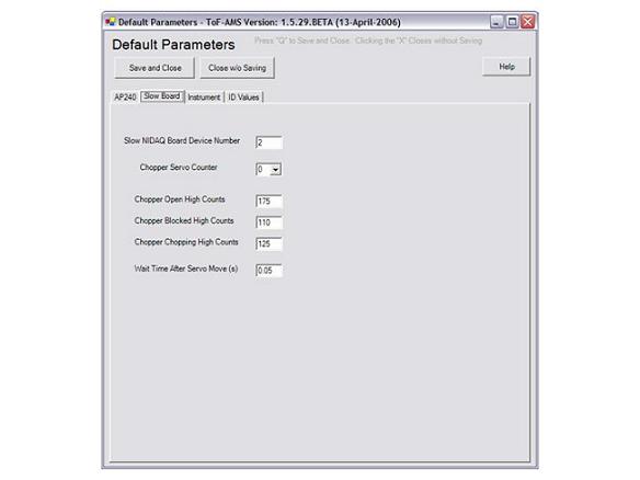
Wait Time After Servo Move The servo moves the chopper each time analysis transitions between beam open, beam closed, or beam chopping. Because this move requires time, acquisition is delayed after any move of the chopper is initiated. This value determines the duration of that wait time in seconds. The default value is 0.500 seconds.
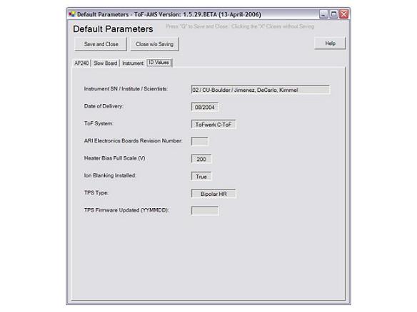
Values read from C:\ToFAMS\ToFAMSCode\ToFAMS_ID.prm are displayed in this tab. Fields are blank if no value exists in the file. Certain of these values control what acquisition options are presented to the user (e.g., ion blanking) and the “heater bias full scale” is used for calibration of the analog control voltage used to set the heater bias.
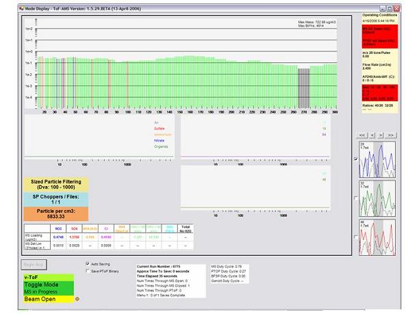
The ToF type may be c, v, or w. This value is set in the default settings window. An incorrect value will not affect performance, but it may create confusion when data is processed. The TOF type is saved within the parameter data for all acquisition runs. And, HDF5 data set names will have extensions indicating the ToF type (nothing for "c", _v for "v", and _w for "w").
The Acquisition Mode indicates the type of data that is currrently being collected. MS-Only, PToF-Only, MS Toggle, etc.
The Chopper State can be Beam Open, Beam Closed, or Chopper Chopped. This value is internal to the software, and cannot be used to determine whether the chopper is functioning properly.
Acquisition State LED
An “LED” in the lower left corner of the screen indicates acquisition status.
And is saved as InfoVal(64).
This value can only be calculated when filtering for all particles or for particles in a defined size range. The displayed number will then represent either the concentration of all particles, or the concentration of particles in the size range. The accuracy of this value depends on concentrations being low enough that recorded data are not coincident particle arrivals.
Active Menu
If menu switching is enabled, a label indicates the current menu number and the number of runs complete / the total number of runs to complete before switching to the next menu.
Duty Cycle Calculations
The acquisition duty cycles for MS, PToF, BFSP, and GenAlt modes are calculated and displayed on in the acquisition window. Duty cycle for each is defined as the time spent acquiring data divided by the time the software spends in the mode. The displayed values are calculated averages for each run. These values are also saved as infoVals(4-7).
Because time spent saving must be included in the total time spent in a mode, the true duty cycle for a run can only be calculated after it is saved. Thus, the first run collected with any menu will not have values for the duty cycle written to the info file. And, the value written to the info file for any run will be that calculated for the previous run. In GenAlt Mode, save times contribute only to the GenAlt Duty Cycle. Thus, duty cycles for MS, PToF, and GenAlt may be lower in mode-only (eg MS-Only) than in GenAlt acquisition.
Resolution Calculation
Diagnostic resolution values are displayed in the labels of the Mode Display window. These
represent the resolution of m/z 14, 28, 91, and 184 in the closed spectrum. These peaks were selected because they
typically have high intensity in the AMS background and because they are dominated by a single compound.
Note that if the background is different at one of these peaks in your instrument (e.g. if two elemental
compositions are present with similar intensity for whatever reason), the reduced resolution reported may
not be meaningful.
These resolutions are calculated as m/dm, where m is the m/z value, and dm is the FWHM of each peak. Note that while important, the resolution is not the only important parameter for peak shape. Issues such as peak tailing can be very important for actual data, but are not captured by this parameter. We hope to add diagnostics for peak tailing in the future.
“Typical” values of resolution for these peaks (for each ToF Type) are hardcoded in the software based on data obtained during testing of prototypes together with the manufacturers of the mass spectrometer (Marc Gonin and Katrin Fuhrer of Tofwerk). The ratios of the current resolutions to these typical values are also displayed. This is meant to give the user an idea of what the resolution should be. If the values are near 1 (0.9 to 1.1), your resolution is near optimal. If it is larger than one, your resolution is better than typical. If the values are lower than ~0.9, your spectrometer could use some tuning. This is most important for the vwToF, but can also be important for the cToF if you try to extract high-resolution information by fitting the peaks.
When the achieved resolutions are significantly lower than the “typical values,” tuning of the Ion Optics and the ToF may be necessary.
Actual resolution values are saved in the info files at indexes 53-56 of the info wave.
Any mass spectrometry instrumentation book will include a discussion of resolution. E.g. see pages 63-64 of the Hoffmann and Strobaant book (Mass Spectrometry: Principles and Applications; Wiley, 2nd edition, 2001).
MS Air BeamLike MS Air Beam, "m/z 28 ions per ToF pulse" reflects transmission. But, this value is indenpendent of ToF pulser frequency. It allows comparison of ion transmission between instruments and for a single instrument as the pulser period is changed (eg, changing between v and w mode).
40/28 and 32/28
These ratios are calculated from the sticks displayed on screen, and can be used as an indication of acquisition card
saturation.
Diagnostic Labels Warning Colors
Diagnostic label colors indicate deviation from Standard Diagnostic Values (To-AMS MENU/Mass Spec Tab).
Orange is moderate and red is substantial deviation. Current values displayed on screen can be stored as Standard
Diagnostic Values by pressing "Control-d." For MS-AB, PToF-AB, and resolution ratios, the moderate
and substantial thresholds are -7 and -15% change, respectively. For flow rate these thresholds are
+/- 3% and 6%.
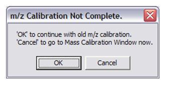
Optional exit to m/z calibration
If mass calibration is not complete before start of PToF, MS, GenAlt, or BFSP
the user has is given the option of continuing and using old calibration or opening the calibration window.
Acquisition does not start until a choice is made.
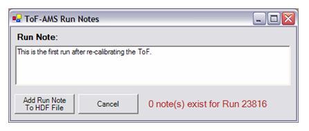
Pressing the "Add Run Note to HDF File" button in Mode Display opens a small Window where users may type Run notes. A given run can have multiple notes. There is currently no limit on how long a note can be, and notes can contain any character. Notes are written as attributes of a dataset called Notes in the currernt *_m.hdf file. If acquisition is stopped before the run is complete, the note is not saved.
For each:
“Brute Force Single Particle” (BFSP) is a mode of the instrument which looks for single particles.
Instead of averaging ~300 chopper cycles together as in PToF mode, this mode looks at only one chopper
cycle.
When run in the “unfiltered” mode, BFSP will save a file for every chopper cycle it acquires, even if there
is no particle present.
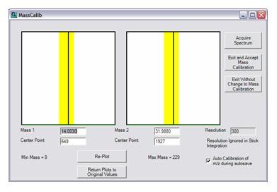
A "closed" spectrum is collected when "Acquire" is pressed. To calibrate, the user inputs the exact mass of two known peaks and the center points of these peaks in nanoseconds. Raw data is displayed at the input center points. The center points values should be adjusted until the vertical lines run through the peak centers. At this point, the user should press "Exit and Accept" to calculate and save the calibration coefficients.
Identifying peaks in these windows requires a previous knowledge of approximate peak locations. Wrongly identifying a peak will produce inaccurate stick data (raw data are not affected by calibration), mass loadings, and air beam values. To find a peak for the first time, display a MSClosed wave in Igor. The x axis of this display has units of nanoseconds, so (x,y) values can be used for (center point, m/z) in the calibration.
Offline Calculation of m/z From Flight Time
Results of the mass calibration calculation are stored as "intercept," InfoVal(44), and "slope," InfoVal(43).
For element number n of a raw mass spectrum wave (.itx):
Note that the trigger delay (ParVal(8))is already included in the intercept.
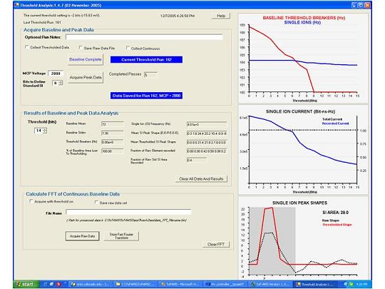
The displayed Current Threshold is read from the parameter menu. This value is used for any thresholded data measurements made from the Threshold analysis window.
The displayed Last Run Number is read from the parameter menu and represents the run number of the last threshold data set saved to disk.
Acquire Baseline and Peak Data
The routine records Baseline Data with the MCP set to a low voltage and Peak Data with the MCP set to acquisition voltages. During a run the user acquires a single baseline data set and peak data sets at all MCP voltages of interest. All data is processed in real-time, and the results are stored as Igor text (.itx) files. In addition, a few key results are displayed in the threshold analysis window. The run number will remain constant until the data is cleared (by pressing Clear All Data and Results) and a new baseline file is collected.
Log File and Optional Run Notes
Information about each run number is stored in the log file, "ThresholdRunsLog.txt." Text entered in Optional Run Notes text box is added to the threshold log file.
Collect Threshold Data
By default, data sets are recorded without any thresholding applied by the Acqiris card. If Collect Threshold Data is checked, complimentary data sets
will be acquired at the current threshold value, which is displayed at the top of the window. The window includes no processing of this thresholded data.
Save Data Files
If Save Data Files is checked, the raw data generated by each button will be saved as binary files (.bin) of 16-bit integers. Saved data files
contain 3.3 msec of unaveraged data (i.e., a single pass). These files will be written to to the directory "c:\ToFAMS\ToFAMSData\ThreshData" and have file names of
the form "runNumber_MCPMCPVolts.bin" and "runNumber_MCPMCPVolts_thbits.bin," for unthresholded and thresholded data,
respectively. Otherwise, the raw data will be disposed of after processing.
Collect Continuously
By default, small portions of data following each MS pulsing event are removed in order to eliminate high-intensity noise associated with the pulsers. If Collect Continuously is checked, the processed and saved raw data will include these portions.
Baseline Data
Before pressing Acquire Baseline Data the MCP voltage should be set to less than 1000V using the ToF voltage control software. All other power should be at acquisition values and the filament should be on. The acquired data should contain only baseline noise (i.e., all signal not originating from ions). The
baseline data is processed at all threshold values between 0 and 15 bits. The results are saved stored in the directory
"C:\ToFAMS\ToFAMSData\ThreshData\RunNumber-CurrentDate-IGOR\" with the file name "runNumber_MCP0.itx." See the table below for descriptions
of the generated waves.
Peak Data
For a given run, the user may acquire peak data at as many MCP voltages as desired. Peak data CANNOT be collected without a current baseline run in memory.
The MCP voltage is set to acquisition voltage using the ToF HV control software. Pressing Acquire Peak Data will start acquisition. Where the baseline
acquisition procedure collects and processes only a single pass, the peak data procedure collects successive passes until stopped. Each pass is processed in
real-time, and the results displayed on the screen are averages of all completed passes. When "Stop Peak Acquisition" is pressed the system will complete the
processing of the current pass and save a single data file containing the averaged processed results. This itx file will be stored in
"C:\ToFAMS\ToFAMSData\ThreshData\RunNumber-CurrentDate-IGOR\" and have a file name of the form "runNumber_MCPVoltage.itx." After this file has
been saved (indicated by message on screen), the user may change MCP voltages and begin peak acquisition again.
Results of Baseline and Peak Data Analysis
Data are processed for threshold values between 0 and 15 bits. Results are displayed for the selected Threshold (bits) value as text.
Baseline Mean
In general, ToF-AMS data is stored with a positive offset, such that the mean of the baseline is non-zero. The Baseline Mean (bits) is calculated as the mean of the values in the raw baseline data. This value is used in the processing of the peak data.
Threshold Breaker
A Threshold Breaker is any acquisition element having intensity (bits) greater than (Baseline Mean + Threshold). The value at the current threshold is displayed as text. And, all values are displayed in the red line in plot 1.
Baseline Area And Percent Lost
Summing the intensities of all acquisition elements greater than the Baseline Mean gives the Baseline Area. The Percent of Baseline Area Lost to Thresholding is calculated by comparing the sum of the intensities of all threshold breakers to the Baseline area.
Ion Arrival Events
Each acquisition element in the peak data is determined to be either baseline noise or an ion arrival. Further, all ion arrivals are determined to be either a single ion arrival or the sum of multiple coincident ion arrivals.
All elements determined to be ion arrivals are classified as either a peak edge or a peak. A peak is defined to be any acquisition element having an intensitity (bits) greater than baseline mean plus the threshold and also greater than the intensities of two acquisition elements adjacent to it.
Single Ion Arrival Events
A Single Ion arrival is defined to be any peak occurring in an acquisition element (i.e., with a time of flight) for which the probability of an ion arrival (peak or edge) is less than 5%.
Numerical values are displayed for Single Ion (SI) Frequency (Hz), Mean Single Ion (SI) Peak Shape, and Mean Thresholded SI Peak Shape at the user-selected threshold setting.
The average Single Ion Frequency for all completed passes is plotted in blue on the top plot.
Peak Shape
The 7 values representing peak shapes correspond to the average values of the 2 rising edge elements preceding single ion peaks (E-E), the elements containing single ion peaks (P),and the three falling edge elements following single ion peaks (E-E-E). See the table below for an explanation of the difference between Mean Single Ion (SI) Peak Shape and Mean Thresholded SI Peak Shape
Standard Single Ion Events
Ultimately, this window aims to find the real single ion events in the raw data and determine how applying a threshold effects those events. Standard Single Ion Events refer to those events in the data thought to be the real single ion events. They satisfy the definition of Single Ion Arrival events when the peak finding algorithm is run at the Threshold to Define Standard Single Ion Events.
Threshold to Define Standard Single Ion Events
To find single ions events, the window first finds all ion arrival events in the data, and then selects those that meet the definition of a single ion arrival event.
The ion arrival event finding algorithm cannot distinguish between peaks originating from ions peaks originating from noise. To help it along, the user sets the threshold to define Standard Single Ion Events, which determines the minimum height necessary to be considered a peak. To be considered an ion arrival event, the identified peak must be greater than this threshold.
If this threshold is set too low, noise peaks will be included in the analysis of the single ion events, and the calculated average area will be too small.
If this threshold is set too high, smaller ion arrival events will be discarded, and the calculated average area will be too large.
Single Ion Area
The mean area of a single ion arrival event is independent of threshold settings; it is defined as the mean
area of the standard single ion events in the unthresholded ("raw") data set.This mean shape is displayed
in black in Plot 2 of the Threshold Analysis window. This area of the mean shape should be used as the
Single Ion Area.
Single Ion Area Lost
Knowledge of the real shape of the single ion events is used to calculate the percent of single ion intensity lost
as threshold is increased. Area is lost when acquisition elements of single ion arrival events have intensities less than the threshold. This effect is a determining factor of dynamic range and linearity. Spectra of low abundance species are recorded as the averages of many single ion arrivals, while spectra of high abundance species are the product of simultaneous ion arrivals. In general, simultaneous ion arrival events produce signals with intensities much greater than our typical threshold settings. Thus, to a first approximation,
thresholding reduces the recorded intensity of low abundance species without significantly affecting the
recorded intensity of high abundance species.
The window includes a text box with the label "Fraction of Raw Standard Single Ion Recorded." This is calculated by direct integratation of the Standard Single Ion Events in the raw and thresholded data. The reported value is the ratio of the sum of all Standard Single Ion Event Acquisition Elements after thresholding and sum of all Standard Single Ion Event Acquisition Elements with no thresholding (i.e., in the raw data).
IMPORTANT: This can be a significant source of bias in ToF-AMS measurements that was not present in the Q-AMS.Thus special attention needs to be paid to setting the threshold and MCP gain (i.e single ion size) properly.
Thresholded Single Ion Shape
The mean shape of the standard single ion events after thresholding is shown in red in plot 2. If a standard single ion event has intensity below the threshold value, it is not included in the calculation of mean shape.
That is, for any given threshold setting, only those standard single ion events that are observed are included in the calculation of mean shape.
Tips For Use of Window
To determine the proper single ion area, the user must set the "Threshold to Define Standard Single Ions" (Thresh-Std-SI) to the lowest threshold at which ion counts dominate background noise. Setting this value properly may require a couple rounds of acquisition. A first guess might be three times the baseline standard deviation, which is reported as text. After acquiring the peak data, the single ion frequency will be displayed. In this plot, the SI Frequency should be at least 20-times greater than the baseline frequency at the "Threshold to Define Standard Single Ions." If the ratio is greater than this, and a lower threshold meets this criterion, the value should be decreased and the peak data recollected. If the ratio is less than this, the value should be increased and the data recollected. The validity of the "Threshold to Define Standard Single Ions" may also be tested by collected data at various values. If the Thresh-Std-SI is slightly too low, the calculated SI Area will jump drastically when the calculation is repeated after increasing the Thresh-Std-SI by 1 bit. (This is because, when the value is too low, noise is confused for single ions). Likewise, if the value can be decreased without causing a significant reduction in the SI Area, the lower value is likely more accurate.
Setting threshold is a balance of limiting noise (baseline threshold breakers) and maintaining a high single ion current. To be quantative for low abundance species, the threshold should be set at a value where the recorded current is close to the total current. Depending on circumstances, this may involve accepting a certain level of baseline threshold breakers. And, the chosen threshold will often be lower than the Thresh-Std-SI.
The raw single ion area, displayed in black in Plot 3, should be used for the single ion area.
.itx Outputs of the Peak and Baseline Data Processing
A unique folder is created for each run number (i.e, Baseline Data Acquisition) with the path
C:\ToFAMS\ToFAMSData\ThreshData\RunNumber-CurrentDate-IGOR\
This folder holds processed baseline and peak data results.
The Baseline data set is processed at thresholds 0 to 15 bits, and the results are stored in an Igor text file withe name runNumber_MCP0.itx This file contains multiple waves, all having names of the form WavePrefix_runNumber. For all except Basehist_, row numbers in the arrays and matrices of the waves correspond to threshold values.
| Wave Prefix | Name | Size & Type | Description |
|---|---|---|---|
| Basehist_ | Baseline Histogram | 1 x (N+1) Array of Integers, where N = the maximum recorded element value | Histogram of all element intensities (bits) recorded during the 3.3-msec baseline acquisition |
| BaseFreq_ | Threshold Breaker Frequency | 1x16 Array of Integers | The frequency (Hz) of acquisition elements having recorded net intensities (recorded intensity – baseline mean) greater than threshold value (bits) equal to the row number |
| BaseAreaHist_ | Baseline Peak Area Histogram | 16 x (N+1) Matrix of Integers, where N = the maximum recorded peak Area | A histogram of the calculated "peak" areas, treating each threshold breaker as a peak and summing |
| BaseAreaMean_ | Baseline Peak Area Mean | 1x16 Array of singles | The mean of the baseline peak area histogram. |
| BaseAreaStdev_ | Baseline Peak Area standard deviation | 1x16 Array of singles | The standard deviation of the baseline peak area histogram. |
| BaseElementProb_ | Baseline Element Probabilities | 16 x N Matrix of singles, where N is the number of elements per ToF spectrum (typically 9984) | The probability that a given element will have a recorded value greater than baseline mean plus threshold in a single extraction. |
For each peak data acquisition (MCP voltage) within a single run, data are processed at thresholds 0 to 15 bits and stored in an Igor text file with name "runNumber_MCPMCPVoltage.itx" This file contains multiple waves, all having names of the form WavePrefix_runNumber_MCPVoltage For all except Datahist_, row numbers in the arrays and matrices of the waves correspond to threshold values. For a given MCP voltage, the saved waves are averages calculated from all completed peak data acquisition passes.
| Wave Prefix | Name | Size & Type | Description |
|---|---|---|---|
| DataHist_ | Data Histogram | 1 x (N+1) Array of integers, where N = the maximum recorded element intensity | Histogram of all element intensities (bits) recorded during the 3.3-msec data acquisition. |
| TotalMS_ | Total Mass Spectrum | 16xN Matrix of singles, where N is the number of elements per ToF spectrum (typically 9984) | Each row average mass spectrum per extraction calculated at the threshold setting equal to the row number |
| pkFreq_ | Peak Frequency | 1x16 Array of integers | The frequency (Hz) of acquisition elements having a net intensity (recorded – baseline mean) that is greater than the threshold equal to the row number and greater than the intensities of the two elements adjacent. (Note that this is not simply the frequency of threshold breakers) |
| SIFreq_ | Single Ion Frequency | 1x16 Array of integers | The frequency (Hz) of acquisition element intensities satisfying the definition of a peak (see above) and occurring in acquisition elements with an element probability (see below) less than 0.05 |
| ElementProb_ | Element Ion Arrival Probability | 16 x N Matrix of singles, where N is the number of elements per ToF spectrum (typically 9984) | The probability that a given element will contain peak intensity (edge or peak) during a single extraction. |
| SIpkShape_ | Single Ion Peak Shape | 16 x 16 Matrix of singles | The 3rd element (column # 2) of each row represents the average intensity of all single ion arrivals for threshold = row number. The first two elements are the average values of the 2 rising edge elements and elements following the peak are the averages of the falling edge elements. ALL edge values, above and below threshold, are included in the calculation, i.e., rising edge elements do not need to be above threshold to contribute to the averaged sum. |
| Thr_SIpkShape_ | Thresholded Single Ion Peak Shape | 16x16 Matrix of singles | Same as _SIpkShape, except ONLY threshold-breaking edges are included in the calculation of average shape |
| Thr_SIpkShapeArea_ | Thresholded Single Ion Peak Shape Area | 16x1 array of singles | The average area of a single ion peak, as calculated by summing the first 7 elements of the relevant row (threshold value) of Thr_SIpkShape_ |
| PkAreaHist_ | Peak Area Histogram | 16 x (N+1) Matrix of integers where N is the maximum recorded peak area | Each row is the averaged histogram of the areas for ALL peaks breaking threshold in all passes. A single area is the sum of 2 rising edge elements, peak element, and 4 falling edge elements. Edge elements must break threshold to be included in the area. |
| SIpkAreaHist_ | Single Ion Peak Area Histogram | 16 x (N+1) Matrix of integers where N is the maximum recorded single ion peak area | Same as _pkAreaHist, but ONLY includes areas of single ion arrivals (see def of single ion in _SIFreq) |
| NetSIpkAreaHist_ | Net Single Ion Peak Area Histogram | 16 x (N+1) Matrix of integers where N is the maximum recorded element intensity, baseline of single ion | Each element is the difference of corresponding elements in the single ion peak area histogram and the baseline peak area histogram (single ion - baseline). |
| SIpkAreaHistMean_ | Single Ion Peak Area Histogram Mean | 16 x 1 array of singles | Single ion peak areas calculated as the mean of the net single ion peak area histograms |
| SIpkAreaHistStd_ | Single Ion Peak Area Histogram Standard Deviation | 16 x 1 array of singles | Standard deviations of the net single ion area histograms. |
| N2Peaks_ | Single Extraction N2 Peak Shapes | N x M matrix of integers, where N = the number of ToF extractions (typically 300) and M = the width of the mass calibrated N2 peaks | (NOTE: NOT YET FUNCTIONING) Each row is a raw N2 Peak recorded in a single ToF extraction. The position of this peak in time space is determined using the current mass calibration. Elements in the displayed peaks are 1 nsec wide. |
Calculate FFT of Continuous Baseline Data
This routine records a single continuous data set (including pulsing events) and performs a fast Fourier transform to identify characteristic frequencies within the noise. In general, the filament should be off during this acquisition. The user chooses whether or not to threshold the acquired data.
By default, only the results of the FFT will be written to disk. The user may choose to save the raw data by checking Save Raw Data.
The user must input a file name. The date and FFT will be added to this name, for instance, 050509_Filename_FFT.bin. No log file exists.
If saved, the Raw Data is composed of 16-bit integers. The _FFT.bin file is composed of floating point singles. All values are low byte first. The output binary file _FFT.bin is an N-element array representing the FFT (magnitude vs. frequency) of the Raw Data. To display data in units of Hz, the array index values should be multiplied by (Sampling Freq/2N). Typical sampling freq = 1 Ghz; Typical N = 2^21
This window records raw mass spectra with no thresholding and steps through thresholds from 0 to 15 bits. The data is processes and and displayed as the signal ratios m/z 40-to-28 and m/z 32-to-28. All data should be collected with filtered air. The display multiplies the 40-to-28 ratio by 10 to put it on the same scale as the 32-to-28 ratio. The display includes a line drawn horizontally at the value determined by the unthresholded data. This is the value that corresponds to the typical ratio for the instrument in it's current state. Raw traces are shown of the difference spectra peaks at m/z 40 and 28.
A text file containing the data is saved in the LogFile directory with the format YYMMDD_mzRatios.txt. In addition all of the raw spectra are saved in the RawSpectra folder within the LogFile Directory with the following name convention: YYMMDD_(thresholdvalue). “Thresholdvalue” takes the value of ThreshOff if Threshold recording was off, or 0-15 depending on the threshold setting.
The results of the m/z ratios are useful for properly setting the MCP voltage and the Acqiris threshold. See Setting MCP Voltage and Threshold Level.
Step 2: *Saturation*
32 to 28 ratio as a function of MCP:
See Figure below for an example (dotted red line is exp. value from W-ToF). This plot shows an obvious saturation trend.
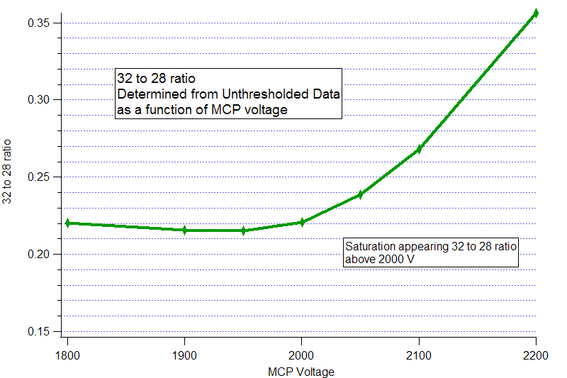
When the MCP voltage increases above 2000 V we see corresponding increases in the 32 to 28 ratio. Essentially this tells us that increasing the MCP above this value could be detrimental to our data quality as large ion signals (big inorganic particles) could be lost. This is (obviously) an argument for addition of the second channel.
Alternatively another simple diagnostic for saturation is the PToF vs MS airbeam. In the event the PToF AB is consistently higher than the MS AB, this is indicative of saturation of m/z 28 for MS mode. This has been verified as a good diagnostic, although no plots have been included.
Step 3: Single Ion Biasing
40 to 28 ratio as a function of threshold:Using the information determined from the 32 to 28 ratio, the MCP in this case should not be set above 2000 V. (As the MCP ages, we would need to set it higher, but under the current conditions, for this instrument, 2000 V is an upper limit.) Now the 40 to 28 ratio as a function of threshold can be examined and the proper threshold can be determined. See below figure.
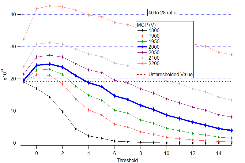
The blue curve in the figure was recorded at an MCP voltage = 2000 V. The point at which the 40 to 28 ratio is equal to the unthresholded data occurs at a threshold of 4. Indicating that the threshold value of 4 is an appropriate setting to run the instrument at.
The Threshold Analysis window provides an independent measure of Single Ion Biasing and can provide verification of appropriate threshold by comparing the Fraction of SI area recorded as a function of threshold.

(I) Pressing “Scan Position” starts a scan of PToF airbeam as a function of the servo position. Each data point represents the measured PToF airbeam for 300 choppers at the servo position indicated on the x-axis. The menu value for wait time after servo move, which is set from the Default Parameter window, is applied between each step. The total scan involves 3 stages:
Possible causes for not observing a top hat shape:
(II) This step is not yet active in the software, but can be carried out manually in MS-Only Acquisition.
To determine the minimum required wait after servo move, the user should measure MS Air Beam values as a function of wait time. The MS AB should be constant for all wait times that are sufficiently long. If the wait time is too short, the transition from MS Open to MS Closed will be blurred, and the recorded MS AB will stray from the real value.
The proper MCP Voltage should be determined first. Because saturation affects large but not small signals, one can detect saturation by comparing the peak area of a stable-concentration large peak to a stable-concentration small peak as a function of MCP voltage. Across the range of MCP voltages where saturation is not occuring, this ratio should be constant. At the point where saturation begins, the small area/large area ratio should begin to increase.
For this diagnostic, we use the first plot of the m/z Ratio Window.
With the MCP voltage set, one must determine where to set the threshold. This decision is based on data collected at the appropriate MCP voltage in both the m/z ratio and Threshold Analysis Windows. The first plot of Threshold Analysis Window shows the frequency of baseline threshold breakers (Hz, red line) as a function of threshold setting. For maximum signal-to-noise, this frequency should be minimized. The efficiency with which baseline noise is discarded can also be quantified by integrating the baseline noise that is not discarded by thresholding. The percent of baseline discarded at the current threshold (set with scroll box) is displayed in a text box in the middle section of the Threshold Analysis Window.
As suggested by rule of thumb #2, setting threshold is a balance of this noise rejection and the need to maintain single ion area. The actual shape of the average single ion is displayed in black in the last plot of the threshold window. The portion of the peak shape included in the area exists within the grey box. As threshold increases, rising and falling edges of single ion peaks may be discarded. And, in the worst case, entire single ion events may be discarded.
The effect of thresholding on single ion arrival events is quantified in both windows. In the Threshold Analysis Window, total single ion area is calculated by summing the area of all standard single ion events in the raw, unthresholded peak data. Percent Single Ion Recorded is calculated by summing the area of the same standard single ion events after applying thresholding. This value is displayed in a text box in the center of the window. To maintain dynamic range, this value should be kept near 1.
Within the m/z Ratio Window, the 40-to-28 ratio and 32-to-28 ratios are plotted as a function of thresholding. The dashed blue and red line represents the "actual" values of these ratios. As threshold increases, an increasing fractioning of the area of the argon peak will be discarded while the area of the 28 peak will remain essentially constant. Therefore, the ratio will fall below the expected value.
It is yet to be determined exactly how much single ion area can "safely" be discarded. But, the aim is to keep the Percent Single Ion Recorded near 100% and the recorded 40-to-28 ratio near its actual value.
A poster with discussion and results focused on ToF-AMS MCP gain and ADC threshold was presented at the 2006 Annual Conference of the American Society for Mass Spectrometry. See: Quantitative Time-of-flight Mass Spectrometry of Aerosols Using a Digitally Thresholded Analog-to-Digital Converter.
Info Values
(0) Time Saved
(1) Sample Time, s
(2) Julian Day
(3) Saving Interval Time
(4) MS Duty Cycle
(5) PToF Duty Cycle
(6) BFSP Duty Cycle
(7) GenAlt Duty Cycle
(8) Time in Single Particle
(9) Number of Samples per Mass Spec
(10) Number of Times through PToF
(11) Fraction of Buffers Saved MS Open
(12) Number of CoAdds
(13) Number of Segments MS
(14) Number of CoAdds PToF
(15) Number of Choppers PToF
(16) Number of Segments PToF
(17) Chopper Frequency
(18) AMS Inlet Flow Rate
(19) Chopper Duty Cycle
(20) MCP Gain
(21) MCP Voltage
(22) Fract Buffers Saved MS Closed
(23) m/z 40 to 28 ratio
(24) m/z 32 to 28 ratio
(25) Average Single Ion Area, bit-ns
(26) Future Value
(27) Future Value
(28) PToFAirBeam, Hz
(29) MSAirBeam, Hz
(30) Average of the CPC (p/cm3)
(31) CPC Std. Dev. (p/cm3)
(32) Number of CPC Readings
(33) Outside Temerature
(35)-(42) Analog Input 0 - 7 (V)
(43) Mass Calibration Slope
(44) Mass Calibration Intercept
(45) AP240 Temerature C
(46) Sulfate ug/m3
(47) Nitrate ug/m3
(48) Ammonium ug/m3
(49) Organic <60 ug/m3
(50) Organics >60 ug/m3
(51) Water ug/m3
(52) Chloride ug/m3
(53) m/z 14 Resolution
(54) m/z 28 Resolution
(55) m/z 91 Resolution
(56) m/z 184 Resolution
(57) Igor Time (since 1/1/1904)
(58) No. Times Through MS Open
(59) No. Times Through MS Closed
(60) Resolution Ratio m/z 14
(61) Resolution Ratio m/z 28
(62) Resolution Ratio m/z 91
(63) Resolution Ratio m/z 184
(64) BFSP concentration per cm3
Instrument ID values follow the info values.
(1) Instrument Serial Number/Scientists
(2) Date of Delivery mm/yyyy
(3) ToF System
(4) Revision Version of ARI Electronics Boards
(5) Heater Bias Full Scale (V)
(6) Ion Blanking Installed
(7) ToF Power Supply Type
(8) TPS Firmware Update mm/dd/yyyy
Menu Values
(1) Off Line Run w/o data acquisition (1: Yes 0: No)
(2) Number of seconds spent in Particle TOF mode in Alternating Mode
(3) Number of seconds spent in Mass Spectrum mode in Alternating Mode
(4) Timer Clock Frequency in MHz
(5) Time of Flight pulser Period in microseconds (us)
(6) High Voltage + pulser width in (ns)
(7) High Voltage - pulser width in (ns)
(8) Delay after chopper before data acquisition starts (us)
(9) Delay after pulser trigger before data is aquired (ns)
(10) Number of TOF spectra acqired per chopper cycle"
(11) Number of choppers to read per average before reading from
(12) Number of points acquired per spectra
(13) Number of Spectra to Co-Add together per segment
(14) Number of chopper cycles to skip
(15) Duty Cycle of the Chopper
(16) Particle Flight distance in the sizing chamber
(17) Serial number of the Acqiris AP240 card
(18) Device Number of the NIDAQ Slow board
(19) Channel 1 Full Scale in Volts
(20) Channel 1 Offset in Volts
(21) Channel 2 Full Scale in Volts
(22) Channel 2 Offset in Volts
(23) Channel 1 Threshold recording on (1=yes 0=no)
(24) Channel 1 Baseline in Volts
(25) Channel 1 Threshold in Volts
(26) Channel 2 Threshold recording on (1=yes 0=no)
(27) Channel 2 Baseline in Volts
(28) Channel 2 Threshold in Volts
(29) Time of averaging before saving to a file
(30) Running number of runs
(31) First Mass used in calibration calculation
(32) ion time of flight bin number for center of Mass 1 peak
(33) Second Mass used in calibration calculation
(34) Ion time of flight bin number for center of Mass 2 peak
(35) Resolution of the Time of Flight Detector
(36) Minimum Mass sampled by current parameter scheme
(37) Maximum Mass sampled by current parameter scheme
(38) Scaling of MS Display
(39) Velocity of Gas after Lens (m/s)
(40) Velocity of Gas in Lens (m/s)
(41) D* for Velocity Calibration (nm)
(42) B (exponential) for Velocity Calibration
(43) Estimated Ionization and Transmission Efficiency
(44) Estimated Single Ion intensity in bits*ns
(45) Default Instrument Flow rate (cc/s)
(46) Default Chopper Frequency (Hz)
(47) Analog Input Channel 0 Slope
(48) Analog Input Channel 1 Slope
(49) Analog Input Channel 2 Slope
(50) Analog Input Channel 3 Slope
(51) Analog Input Channel 4 Slope
(52) Analog Input Channel 5 Slope
(53) Analog Input Channel 6 Slope
(54) Analog Input Channel 7 Slope
(55) Analog Input Channel 0 Intercept
(56) Analog Input Channel 1 Intercept
(57) Analog Input Channel 2 Intercept
(58) Analog Input Channel 3 Intercept
(59) Analog Input Channel 4 Intercept
(60) Analog Input Channel 5 Intercept
(61) Analog Input Channel 6 Intercept
(62) Analog Input Channel 7 Intercept
(63) Analog Input Channel 0 Voltage Range
(64) Analog Input Channel 1 Voltage Range
(65) Analog Input Channel 2 Voltage Range
(66) Analog Input Channel 3 Voltage Range
(67) Analog Input Channel 4 Voltage Range
(68) Analog Input Channel 5 Voltage Range
(69) Analog Input Channel 6 Voltage Range
(70) Analog Input Channel 7 Voltage Range
(71) Low MS mass for display
(72) High MS mass for display
(73) Timing Offset between MS and PToF modes
(74) Threshold window run number
(75) Chopper Open Count
(76) Chopper Blocked Counts
(77) Chopper Chopping Counts
(78) User Defined High Operating Temperature of the AP240 (C)
(79) Number of Seconds Spent in BFSP in Alternation Mode
(80) Determines whether PToF is active in Alternation Mode (1: Yes 0: No)
(81) Determines whether MS is active in Alternation Mode (1: Yes 0: No)
(82) Determines whether BFSP is active in Alternation Mode (1: Yes 0: No)
(83) Number of seconds spent averaging on the AP240in MS mode
(84) Determines whether AutoSave is on (1: Yes 0: No)
(85) Determines whether to save PToF Binary Data (1: Yes 0: No)
(86) Determines the Percentage (Value 0-100) of the Time MS is Open (instead of Closed)
(87) The wait time (in Seconds) after setting the Pulser Timers
(88) The wait time (in Seconds) after setting the Acquisition Trigger Timers
(89) Determines whether or not to save on a fixed grid in time (1: Yes 0: No)
(90) m/z 1 for raw resolution display in Mode Display window
(91) m/z 2 for raw resolution display in Mode Display window
(92) m/z 3 for raw resolution display in Mode Display window
(93) Wait Time after Save to reinitialize (Seconds)
(94) Mode in which ToF is used (0=C-ToF, 1=V-ToF, 2=W-ToF)
(95) Servo Counter on Slow Board (0 or 1)
(96) Transient Saving On (1: Yes 0: No)
(97) Filter BFSP data before saving to Disk (1: Yes 0: No)
(98) Save BFSP binary Data (1: Yes 0: No)
(99) The standard measured value of the MS Air Beam (Hz)
(100) The standard measured value of the PToF Air Beam (Hz)
(101) The standard measured value of the flow rate (cm3/sec)
(102) Delay after start of acquisition before updating diagnostic label colors
(103) The standard measured value of the m/z 14 Resolution Ratio
(104) The standard measured value of the m/z 28 Resolution Ratio
(105) The standard measured value of the m/z 91 Resolution Ratio
(106) The standard measured value of the m/z 184 Resolution Ratio
(107) Determines whether data is written in HDF Format (1: Yes 0: No)
(108) Determines whether data is written in IGOR Text Format (1: Yes 0: No)
(109) The maximum allowable size for an extendible HDF File (MB)
(110) Determines whether to write data to TimeTrace.txt
(111) CH2AcquireMode: Defines the CH2 acquisition mode (0: No acquisition 1: Standard 2: CH1 Offscale)
(112) CH2BFSPSaveType: Type(s) of BFSP data to save for CH2 (0: Stick, 1: Binary, 2: Both)
(113) CH2PToFSaveType: Type(s) of PToF data to save for CH2 (0: Stick, 1: Binary, 2: Both)
(114) BandwidthCh1: Sets the bandwidth (MHz) for AP240 CH1 (0=1000;2=700;3=200;4=20)
(115) BandwidthCh2: Sets the bandwidth (MHz) for AP240 CH2 (0=1000;2=700;3=200;4=20)
(116) IonBlanking: Determines whether ion blanking is active (1: Yes 0: No)
(117) IonBlankTime: The flight time at which ion blanking begins (ns)
(118) IonBlankDuration: The duration of the ion blanking pulse (ns)
(119) NegativeIonMode: Sets software for negative ion acquisition (1: Neg Ion 0: Pos Ion)
(120) MCPGainFactor: Ratio of amplified signal intensities reaching AP240: CH1/CH2
(121) BFSPMinSize: Minimum Dva (nm) for BFSP Size Filtering is applied
(122) BFSPMaxSize: Maximum Dva (nm) for BFSP Size Filtering is applied
(123) CalibrationSpecies: Chemical Species for calibration (0=NH4NO3, 1=(NH4)2SO4)
(124) BFSPCH2RowSum: Sum of BFSP CH2 row to use a threshold for data filtering
(125) menuSwitching: Determines whether menus are switched automatically (1: Yes 0:No)
(126) menu1ActiveSwitching: Determines whether menus 1 is active during automatic menu switching (1:Yes 0:No)
(127) menu2ActiveSwitching: Determines whether menus 2 is active during automatic menu switching (1:Yes 0:No)
(128) menu3ActiveSwitching: Determines whether menus 3 is active during automatic menu switching (1:Yes 0:No)
(129) menu4ActiveSwitching: Determines whether menus 4 is active during automatic menu switching (1:Yes 0:No)
(130) menu1NmbrSwitch: No. of runs spent in Menu 1 if active during automatic menu switching (sec)
(131) menu2NmbrSwitch: No. of runs spent in Menu 2 if active during automatic menu switching (sec)
(132) menu3NmbrSwitch: No. of runs spent in Menu 3 if active during automatic menu switching (sec)
(133) menu4NmbrSwitch: No. of runs spent in Menu 4 if active during automatic menu switching (sec)
(134) invertCH1: Configure AP240 CH1 for inverted data acquisition (1: Yes 0:No)
(135) invertCH2: Configure AP240 CH2 for inverted data acquisition (1: Yes 0:No)
(136) noiseFilterThresh: Threshold (bits) for noise filtered spectral rejection (+: Enable -:None)
(137) heaterBiasV: Heater bias voltage
(138) WaitAfterServo: Wait Time after Servo Move (seconds)
(139) Reflectron Back Plate Voltage
(140) Reflectron Grid Voltage
(141) Lens Voltage
(142) Hard Mirror Voltage
(143) Post Acceleration Voltage
(144) MCP Voltage
(145) Pulser U-Low Voltage
(146) Pulser U-High Voltage
(147) Pulser U+Low Voltage
(148) Pulser U+High Voltage
(149) Lens 2 Voltage
(150) Deflector Voltage
(151) Deflector Flange Voltage
(152) Ion Exit Voltage
(153) Lens 1 Voltage
(154) Electron Pusher Voltage
(155) Ion Chamber Voltage
(156) Filament Voltage
(157) Filament Current
(158) Filament Current Limit
(159) Active Filament (0=Fil1; 1=Fil2)
(160) WaitAfterMenuSwitch
(161) WaitAfterPolaritySwitch
CH2 Data
If CH2 is enabled for any acquisition type (MS, PToF, or BFSP), CH2 data waves are included in the *.itx files. Waves have the same names as the corresponding CH1 data plus the extension _CH2.
CH2 binary data are stored to unique files having the same names as CH1 data plus the extension _CH2.
File Names and Types
ToF-AMS acquisition software versions 1.5 can write PToF and MS data as extendible HDF5 files, with datasets corresponding to the waves of the standard ToF-AMS itx files (e.g., "InfoVal," "ParVal," and "MSopen."). A single HDF5 file contains multiple runs, written as the layers of the datasets. Groups are not used in the ToF-AMS data structure.
HDF5 data is written to the directories C:\ToFAMS\ToFAMSData\AutoSaveDataHDF and C:\ToFAMS\ToFAMSData\NonAutoSaveDataHDF. Within each are the sub-directories \Main and \PToF. HDF file names include the acquisition date, the first run number written to the file (as 6 digits), and the type of data in the file (p = ptof, m = main).
As an example, autosaving data on Oct 31, 2005 and beginning with run number 100 would generate the files:
_p.hdf files include the datasets: InfoVal, ParVal, RunInfo, and PToF
In both *_m.hdf and *_p.hdf files, text descriptions of the values (i.e., InfoText and ParStr) are written as attributes of the datasets InfoVal and ParVal.
If CH2 is enabled for MS or PToF mode, CH2 data sets are included in the *_m.hdf and *_.p.hdf files. Dataset have the same names as the corresponding CH1 data plus the extension _CH2.
A single HDF file may contain both w- and v-mode data. Datasets MSSDiff, MSDiff, MSopen, ptof_stick, and PToF are given extensions to indicate the ToF type.
_m files:
Starting New Files
A new set of HDF files is started each time the software loads. A given set of HDF files (_p and _m) will be written to until one of the files exceeds the maximum file size (defined in the Menu Parameter), the acquisition date changes, or the dimensions of a dataset within the file changes between runs (e.g., the MS Sticks array grows or shrinks).
Run Notes
Run notes can be added to an HDF file during acquisition.
Pressing the "Add Run Note to HDF File" button in Mode Display opens a small Run Notes Window where users type their notes.

A given run can have multiple notes.
If the user adds run notes during acquisition, a dataset called Notes will be added to the *_m.hdf file containing the run(s) for which notes exist.
Notes are written as attributes the dataset Notes in the currernt *_m.hdf file.
Attribute names are of the form: r23706_Note_0, r23706_Note_1, and so on (where 23706 is the run number, Note_0 is the first note for the run number, and Note_1 is the second note for the run number)
The values of the note attributes are written in the form: YYMMDD_HHMM_RunNumber_NoteText. For instance, the note shown above would be written as: "051215_1135_23816_This is the first run after re-calibrating the ToF." with the attribute name r23816_Note_0.
If acquisition is stopped before the run is complete, the note is not saved.
Viewing HDF Files
All HDF data can be viewed and processed using the HDF5XOP available with Igor Pro 5.04.
The set of .itx and .bin files to be converted is chosen by selecting the info.itx files corresponding to the first and last runs of interest. Run numbers within the desired set of files do not need to be contiguous and the set of files can cover multiple dates. But, info.itx must exist for all runs to be converted. PToF.bin cannot be accurately converted without an associated PToF.itx file.
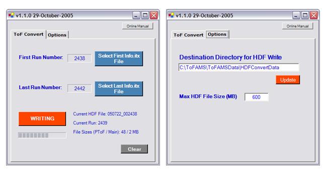
Within the options tab, the user defines the maximum HDF file size and the destination directory for converted HDF data. The sub-directories \Main and \PToF will automatically be created within the destination directory.
As an example, writing to the destination directory C:\ToFAMS\ToFAMSData\HDFConvertData and starting the conversion with file 103105_100_Info.itx will generate the files:
A line is written to the file for each run that includes: time of save, air beam values, loadings, and MS intensities for m/z 43, 44, 57, and 10 user-selected values.
The first 14 columns of TimeTrace.txt are constant. These are:
The final 20 columns of TimeTrace.txt are dedicated to 10 user-selected m/z values. For each, there is a column identifying the m/z value and a column reporting the intensity of the m/z value. For instance, user-selected m/z #1 has columns "usmz_1" and "Iusmz_1."
The user-selected m/z values default to: m/z = 30, 41, 46, 48, 55, 64, 69, 77, 91, and 202. These 10 values can be changed in ToF-AMS Menu Parameter Window.