ToF-AMS Orifi
Pressure Controlled Inlet Discussion
This page was first setup by Mike Cubison, Feb 2008
Further to discussions at the 2007 AMS Users Meeting and AAAR, a new version of the PCI has been developed for use with the AMS (or anything else using an aerodynamic lens) in situations where one needs to sample over a large range of ambient pressures.
Principle
1) Keep the pressure at a fixed value in a PCI chamber directly upstream of the AMS pinhole (orifice). 2) A critical orifice upstream of the PCI chamber provides a pressure drop from ambient to a lower, controlled (fixed) value ==> as ambient pressure changes, the mass flow into the PCI chamber will vary also ==> by pumping away the excess mass flow over that required by the AMS, the PCI chamber can be maintained at a fixed pressure. 3) The fixed pressure has to be >= the minimum anticipated sampled atmospheric pressure to maintain sample flow.
SO... the operating parameters are defined by
1) The mass flow rate required by the AMS 2) The minimum sampling pressure (>= PCI chamber pressure)
e.g. For a standard AMS needing a mass flow of 1.4e-4 kg min-1 (0.14 lpm at sea level):
At 40,000ft, ambient pressure is ~ 175 mbar. At the max altitude, there is no bypass flow, thus 1.4e-4 kg min-1 flows into the PCI. At 175 mb this is 0.82 lpm. This volumetric flow is conserved as the ambient pressure increases!
So, at sea level (and including some for RAM pressure on an aircraft), ambient pressure has increased to 1060 mbar. Volumetric flow into the PCI is CONSERVED at 0.82 lpm. This is 8.5e-4 kg min-1 at 1060 mb, giving a surplus over the 1.4e-4 kg min-1 needed by the AMS of 7.1e-4 kg min-1.
If this surplus is not pumped away, the PCI pressure would increase, increasing the mass flow into the AMS and risking frying pump 2... therefore, a PCI bypass pump is required that can shift 7.1e-4 kg min-1 at PCI pressure.
PCI design
Several PCI designs have been used in the past few years. Perhaps the simplest is that deployed by Steve Howell and Tony Clarke from U of HI. Design to be posted pending approval... :)
PCI orifi
(I distinguish here between the orifice upstream of the PCI chamber "PCI orifice" and that upstream of the lens "AMS pinhole").
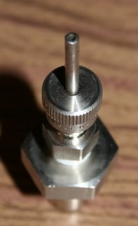
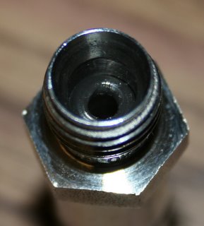
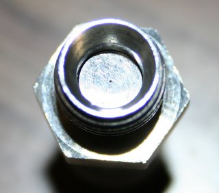
Traditionally, flat disc orifi made by SPI Inc. have been used for the AMS pinhole (~100-150 um at typical operating altitudes). O'Keefe manufacture 1/4" tube orifi that fit easily in swagelok, but at least in my (MJC) experience, they are not built to fine enough tolerance to deliver good aerosol transmission. The J-Group uses two SPI orifi in the CU PCI, a 250 um PCI orifice and a 300 um pinhole (for a 160mb PCI).
Mounting:
Again, traditionally, the SPI orifi have been mounted in a modified 1/8" ultratorr fitting system, thus:
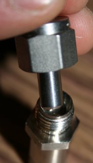
For the PCI, the 1/8" system has proven pretty delicate... so I (MJC) have been using a different mounting protocol for the SPIs in the CU PCI, directly into a 1/4" swage fitting using a 1/8" ultratorr O-ring and nylon ferrules. This has the advantage of providing a larger tube upstream of the orifice, reducing the velocity of the flow and theoretically improving transmission... and moreover, the downstream tube is larger and can be kept short... in fact, the downstrea tube is anything you like, so long as there is a 1/4" swage on top. Example using a 1/2" tube to 1/4" female swage piece:
Operational PCI Losses
Roya Bahreini and co-workers (in press 2008) showed how the AMS transmission (sampled cm-3 compared to real cm-3) decreases going to lower PCI pressures. It was demonstrated that the losses did not occur in the PCI, and it was assumed the loss region was impaction on the tube immediately after the AMS pinhole.
MJC made some basic calculations based on the work of Chen et al. (2007), which showed massive theoretical impaction losses in the tube-after-orifice (TAO) for low upstream pressures (like when using a PCI). Based on this, Peter McMurry and Xiaoliang Wang of UMN/TSI agreed to model the flow stream thru the AMS pinhole with low upstream pressure, showing indeed that the TAO was a significant loss region. An expansion chamber was designed based on the calculations of Xiaoliang which sits immediately above the AMS inlet:
The expansion chamber allows for expansion of the flow without severe impaction and the taper reduces recirculation. Initial tests are showing 100% transmission over the AMS operational diameter range for a 160 mbar PCI chamber.


